AGRIGLOBE / Smart Retrofit

From A Working Need.
To A Validated Solution.

Custom agricultural electrical control systems and innovative applications. A structured service process guides the work from requirements to integration, testing and handover.

Built Around Your Operation

Practical Intelligence.
Careful Integration.

Every machine and operation is different. We begin with the existing equipment, the intended function and its operating conditions to define a realistic project scope.

Discuss a retrofit project
Agricultural Systems / Custom Engineering
REQUIREMENT-LEDINTEGRATED & VALIDATED
Custom Retrofit Concepts

Two Ways To Upgrade The Machines At Work.

Custom controls can connect machine status, settings and actuation; seed-spacing control can link travel speed with seed metering. These examples show a possible project scope, tailored to the machine and task.

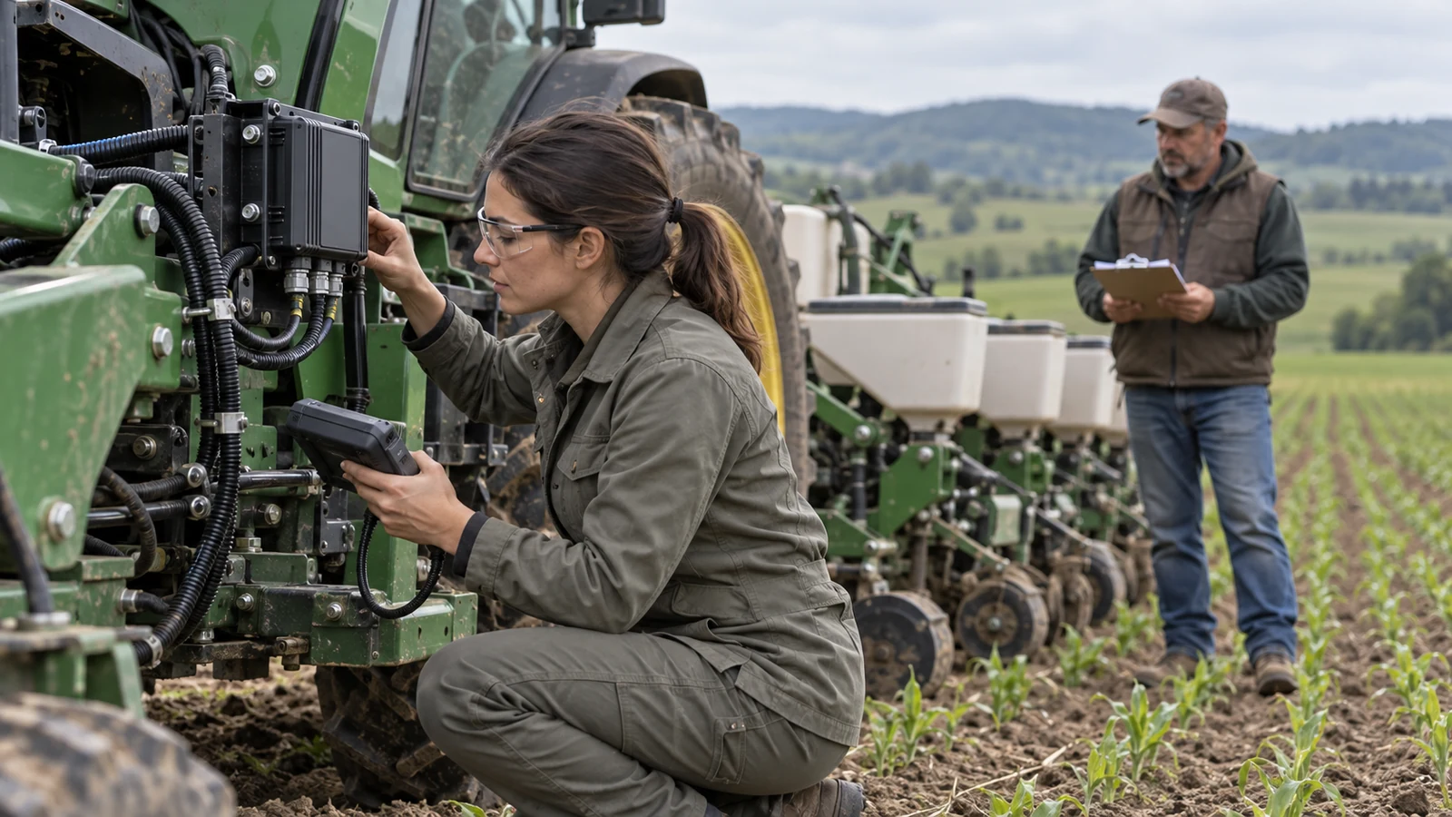
Illustrative agricultural controller, wiring and operator interface integration
01

Agricultural Smart Control System

Connect sensors, a controller, actuators and an operator interface around an agreed task. The aim is to make key machine states visible and control behaviour easier to set, check and maintain.

How The System Works
  1. 1Sense Machine Status
  2. 2Apply Control Logic
  3. 3Adjust The Actuator
  4. 4Show Operator Feedback
Operating Need
For machines with dispersed controls, limited status feedback or a task that would benefit from electronic coordination.
Possible Configuration
A matched controller, relevant sensors, protected power supply, wiring and operator display. Existing electrical, hydraulic or communication interfaces are assessed before the configuration is agreed.
Integration And Verification
Confirm input/output behaviour and control responses on a bench, then integrate with the machine. Check relevant fault states and representative operating conditions against the agreed test plan.
Agreed Handover
Agreed system configuration, wiring and interface notes, software or parameter version, operating guidance and project-specific test records.

Illustrative electric seed-meter drive on a planter row unit
02

Seed Spacing Control System

For suitable precision planters, combine a reliable travel-speed input, a matched seed-meter drive and seed monitoring. Adjust the metering rhythm around the target seed spacing and review the resulting planting performance.

How The System Works
  1. 1Read Travel Speed
  2. 2Regulate Seed Metering
  3. 3Monitor Seed Delivery
  4. 4Calibrate And Check
Operating Need
For equipment where speed changes complicate seed-spacing control or operators need clearer feedback on missed, doubled or stopped seed delivery.
Possible Configuration
Assess seed type, seed-meter design, drive ratio, row configuration, power supply and installation space. The proposed setup may combine a controller, electric drive, speed source, seed sensors and a setting interface.
Integration And Verification
Calibrate speed, drive and metering behaviour. Check steady speeds, acceleration, stops and relevant faults, then sample actual seed spacing and missed or double drops in the field under agreed conditions.
Agreed Handover
A confirmed retrofit configuration, calibration parameters, installation and operation guidance, plus agreed bench and field test records.

Seed spacing is the distance between successive seeds along the direction of travel; it does not mean automatic adjustment of row spacing. Actual results also depend on seed separation, the drop path, speed and field conditions.

Illustrative project concepts, not claims of previously delivered projects. Functions, fitment, test conditions and acceptance criteria are agreed for each machine.

Illustrative business scenes show the type of work discussed. They do not represent company-owned facilities or a specific delivered project.

Service Process

A Clear Path
From Idea To Operation.

Project scope, deliverables and validation checks are agreed around your machine and intended use.

01

Listen & Assess

Understand the machine, current operation and the improvement you want to achieve.

02

Define The Scope

Agree the functional requirements, technical boundaries and acceptance criteria.

03

Design The Solution

Develop a project-specific control and integration approach for review.

04

Integrate The System

Carry out the agreed changes and check the relevant machine interfaces.

05

Validate & Test

Check function and reliability against the agreed conditions and test plan.

06

Handover & Support

Review the results, clarify operation and agree any follow-up service.

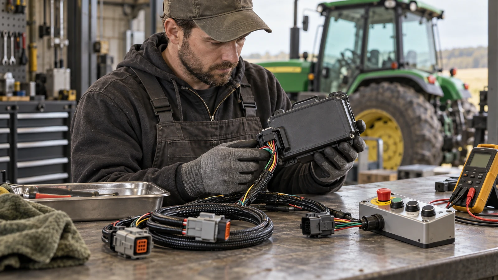
Illustrative technician checking a controller installation beside farm machinery
From Bench To Working Conditions

Reliable Operation Starts With A Clear Test Plan.

The project is reviewed against agreed functions, interfaces and operating conditions. Relevant bench checks and machine tests are planned around the scope, with results and remaining limits discussed before handover.

A useful handover includes the agreed configuration, operating guidance, maintenance considerations and follow-up arrangements.

Function & Integration

Check intended control behaviour, interfaces and interaction with the existing machine systems.

Operating Conditions & Handover

Review performance in the agreed operating conditions, document the results and explain the relevant use and maintenance requirements.

Each project is assessed individually. Functions, testing scope and support arrangements are agreed before work begins.

Let’s Build A Working Relationship

Your Next Season.
Our Next Conversation.

Tell us what you work with, what you need and where it needs to go.